Indoor test facility
With the Indoor test facility, new sensor systems and safety functions are tested in road trials and crash tests under constant ambient conditions. Driving tests with complete vehicles are carried out with the help of a driving robot using an indoor location system in the low to medium dynamic range (up to 50 km/h). For this purpose, dummies (e.g. pedestrian, vehicle) mounted on traversable, autonomous platform robots are used.
Goals and idea
The main advantage of indoor operation is the constant ambient conditions. Particularly with regard to the effects of disturbing influences on anticipatory vehicle sensors, the ambient conditions can be changed in a targeted manner (lighting, rain, fog). Several networked driving robot systems with extended safety mechanisms will be available for testing new cooperative safety functions in the entire vehicle. In addition, an integral test approach should make it possible to combine driving tests and crashes. Real driving tests can be modified by feeding simulated (environment) sensor data into the moving complete vehicle up to a virtual crash (Vehicle-in-the-Loop).
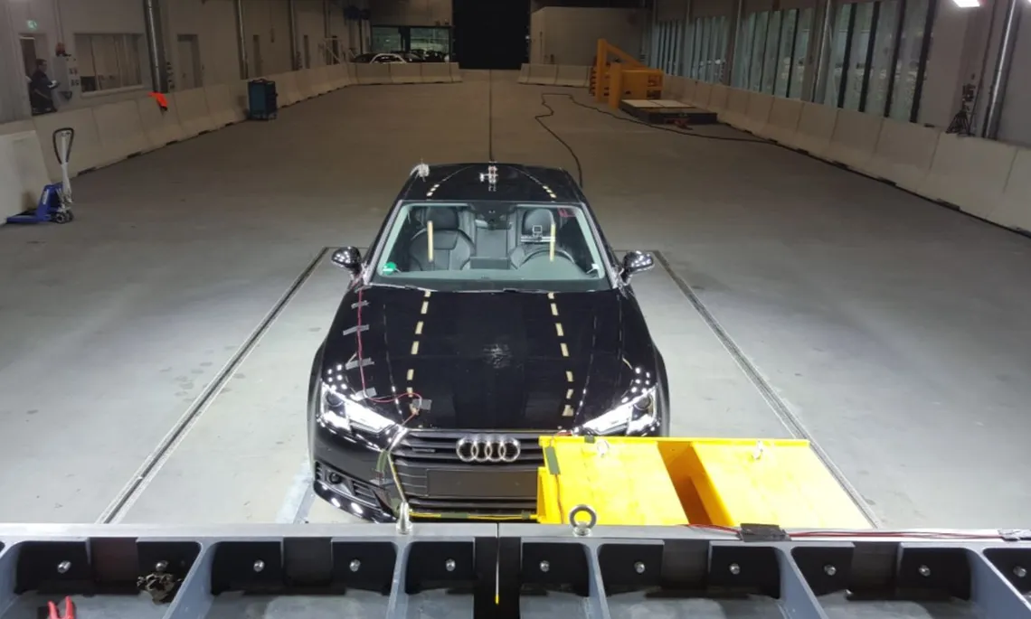
Crash system
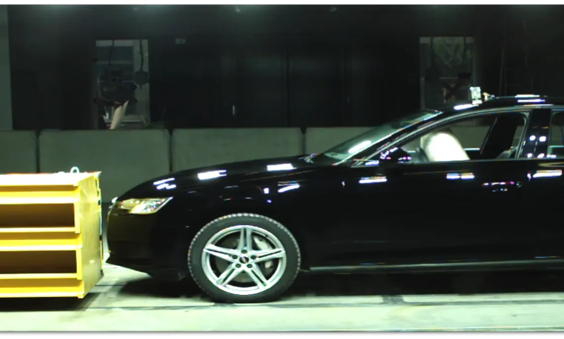
Crash with predictive airbag deployment
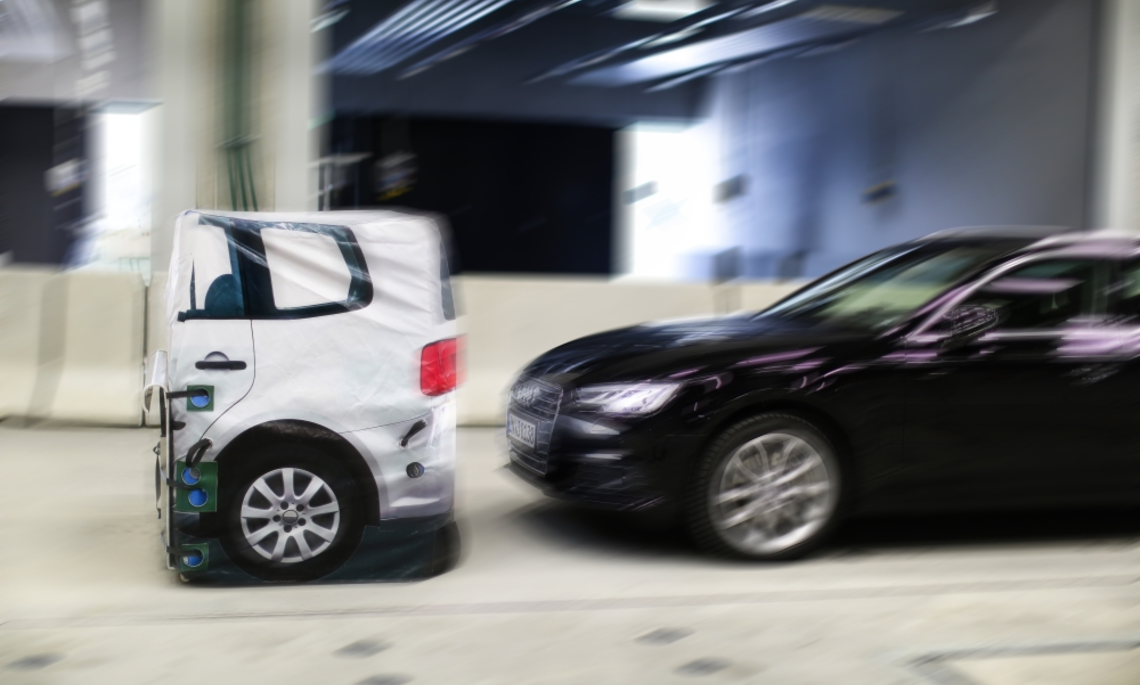
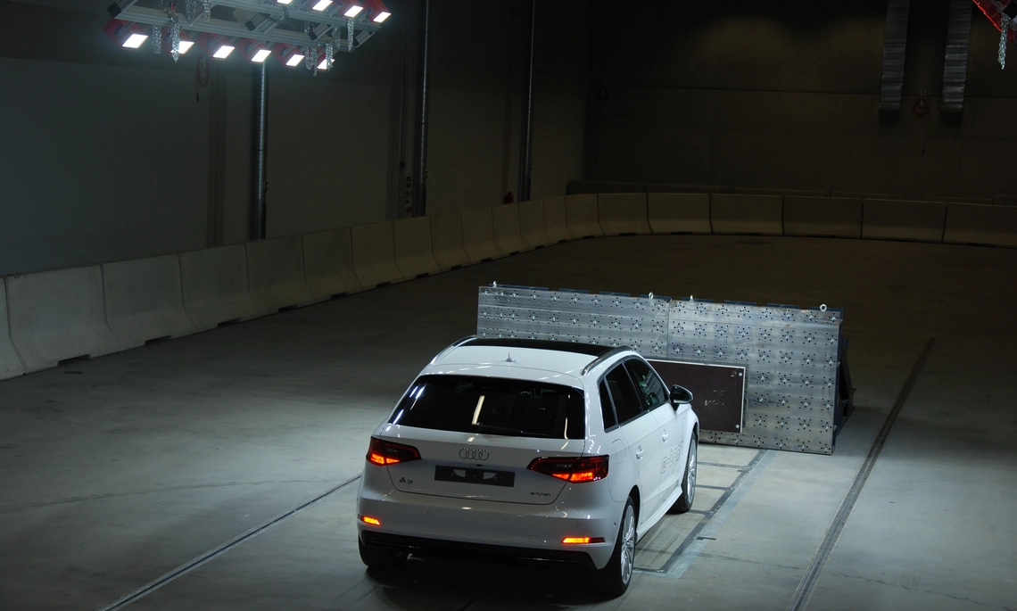
AEB-Target
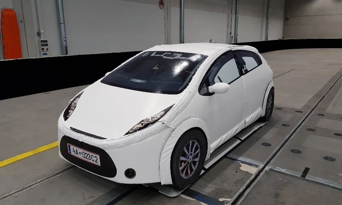
Vehicle target
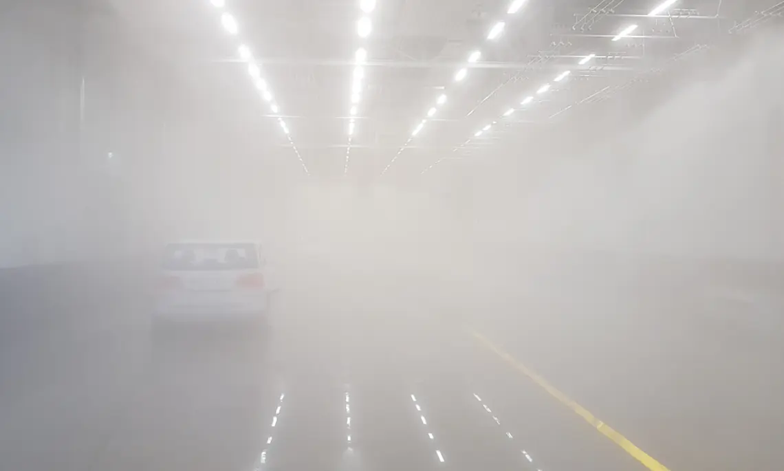
Fog system
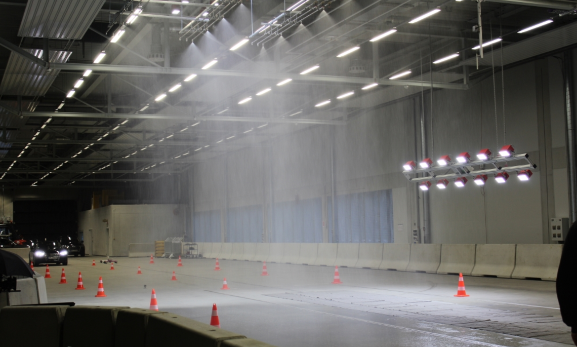
Rain in the experimental hall
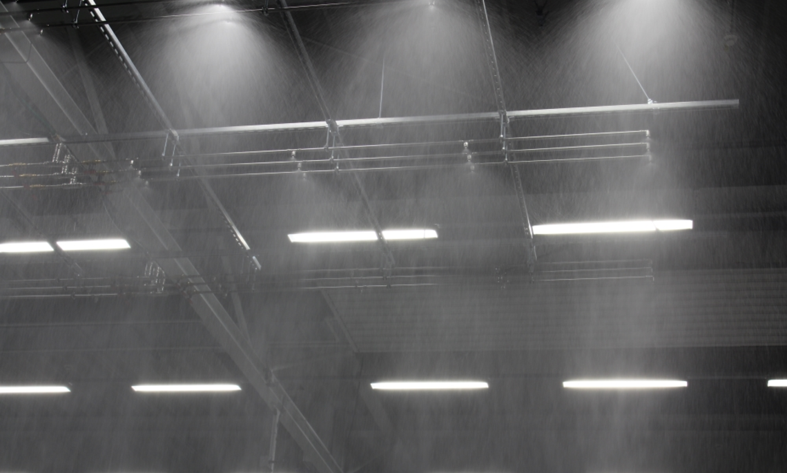
Rain system
Radar-capable hall
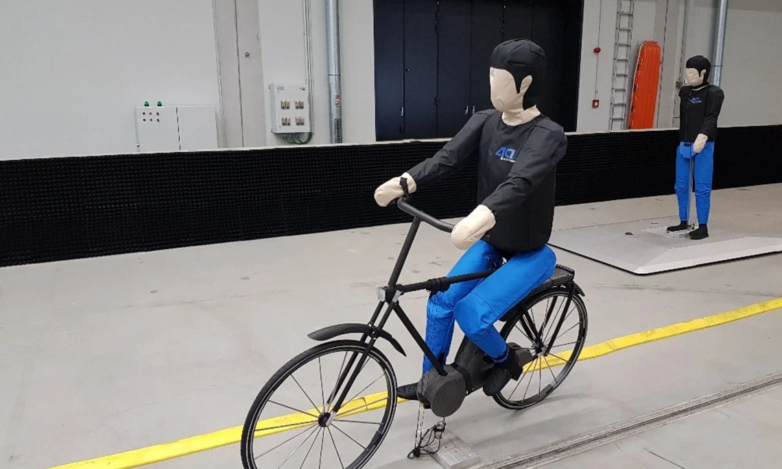
Target cyclist
Multifunctional C-ISAFE test hall
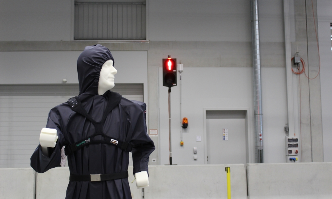
Pedestrian dummy and traffic lights
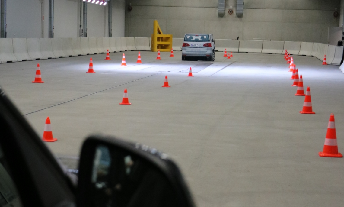
View into the C-ISAFE test hall
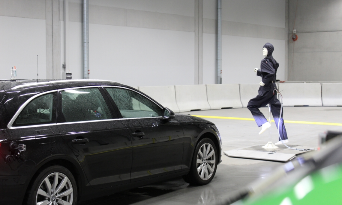
Road test with C-ISAFE pedestrian dummy and mobile robot platform
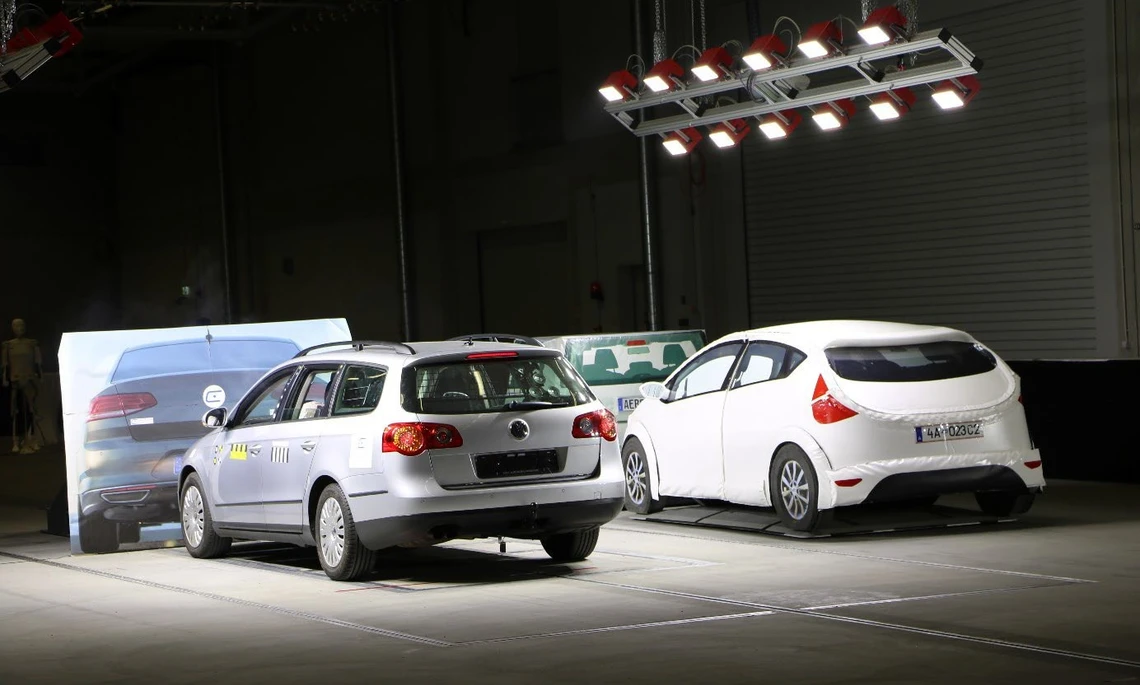
Integral crash test in Indoor test facility
Equipment
With the help of the rain facility in the indoor test hall, realistic rain scenarios can be simulated. Details can be found in the illustration of the rain system.
With the help of the fog system in the indoor experimental hall, realistic fog scenarios can be simulated from water particles. Details can be found in the illustration of the fog system.
With the help of the light system in the indoor experimental hall, realistic light can be simulated. Details can be found in the illustration of the light system.
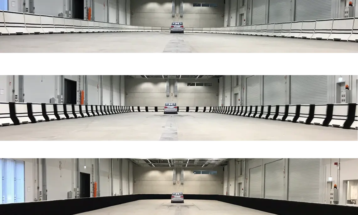
A variety of targets are available to recreate a wide range of traffic scenarios. Details can be found on the targets website.
For crash tests, the researchers have access to a state-of-the-art cable-operated crash facility including a film pit. Details can be found on the crash system website.
For automated driving tests and positioning systems of refernce, details can be found on the website of the free drive systems for automated road tests.
Examples of use
- Crash tests with complete vehicle and components
- Continuous crash tests (with pre-crash phase)
- Vehicle tests with rain and fog
- Selective disturbance of environmental sensor technology with rain and fog
- Accident situations for validation of predictive vehicle safety functions with camera, radar, lidar sensors etc.
- Cooperative vehicle safety functions with networked sensor systems and Car2X
Laboratory management and team

Prof. Dr.-Ing. Thomas Brandmeier
Phone: +49 841 9348-3840
Room: H023
E-Mail: Thomas.Brandmeier@thi.de

Christoph Trost, M.Eng.
Phone: +49 841 9348-3384
Room: H120
E-Mail: Christoph.Trost@carissma.eu

![[Translate to English:] Logo Akkreditierungsrat: Systemakkreditiert](/fileadmin/_processed_/2/8/csm_AR-Siegel_Systemakkreditierung_bc4ea3377d.webp)