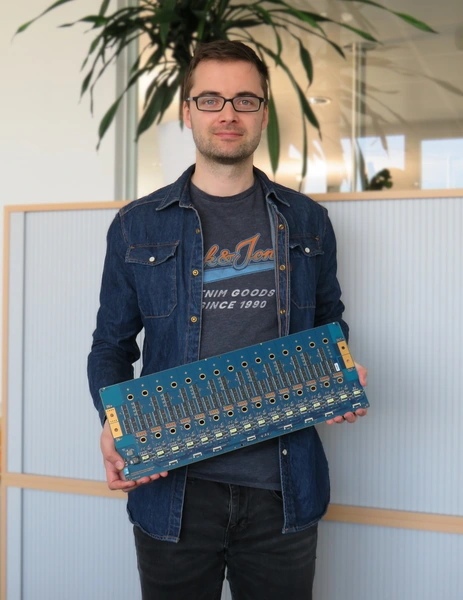
In our Electromobility and Learning Systems (ELS) research group, a circuit board prototype with the novel PECIN switch structure has been completed as part of a complete test bench.
The setup of the multilevel inverter test bench is used to evaluate different switch structures, system concepts, such as optimal step height, and actuation methods. Among other things, the various multilevel inverters are to be compared in terms of their system efficiency with that of a conventional three-phase two-point inverter.
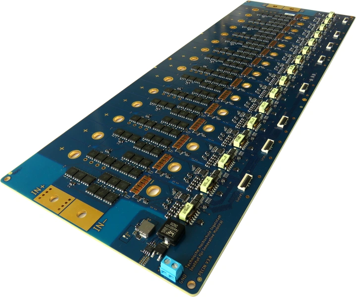
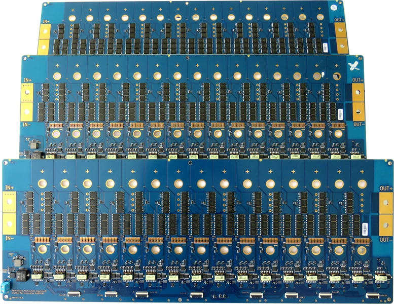
The circuit diagram and layout of the board were developed entirely in-house. The board is a modular board, which allows 15 prismatic lithium-ion cells to be connected in parallel or series, depending on the current and voltage requirements. This results in voltages of about 60 V per module board. A serial interconnection of several module boards allows a higher system voltage.
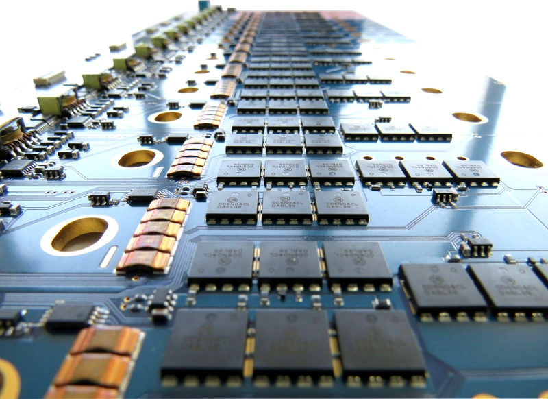
Three low-voltage power MOSFETs are paralleled per switch of the PECIN switch structure. This allows the drain-source on-state resistance to be dramatically reduced. To keep the copper resistance of the board low, copper inlays with a thickness of 1 mm and 2.5 mm are used alternately. This achieves electrical resistances in the range of a few hundred micro ohms, allowing hundreds of amps without active cooling, according to FEM simulation. Voltage and current are recorded from each cell at a frequency of 1MHz and processed centrally.
One of the next steps is to commission the hardware to subsequently validate SPICE, Simulink and FEM models at the board level. After completion of the remaining components of the test bench, different operating strategies and modulation types will be investigated in order to be able to give a statement regarding optimal system design.

![[Translate to English:] Logo Akkreditierungsrat: Systemakkreditiert](/fileadmin/_processed_/2/8/csm_AR-Siegel_Systemakkreditierung_bc4ea3377d.webp)


![[Translate to English:] Logo IHK Ausbildungsbetrieb 2023](/fileadmin/_processed_/6/0/csm_IHK_Ausbildungsbetrieb_digital_2023_6850f47537.webp)